22 March 2017
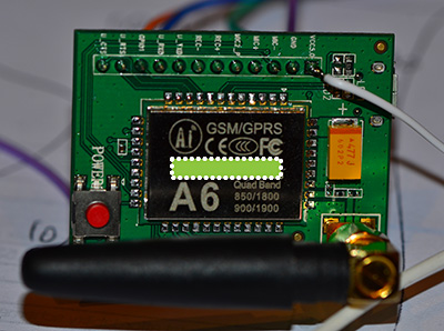
If only things work like they should then I dont need to write these articles. haha. I bought an A6 GSM module from Aliexpress and it was like only 5 dollars - I wanted to use it to send SMS text messages within our Home Automation system.
What supposed to happen is that - when you put a SIM card in the module and provide USB power, you should be able to ring through to that number from another phone / mobile. On mine, no such luck as the A6 refused to connect to the network.
Bugger if I know! So in order to debug the A6 Module, I use a PL2303HX USB to TTL module to link up the A6 Module to my computer.
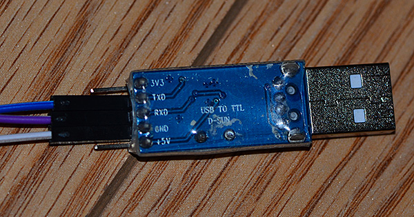
So simply hook up the RX, TX and Ground pin between the A6 Module and the TTL Module. Dont forget to have one Rx Pin going into the other Tx Pin.
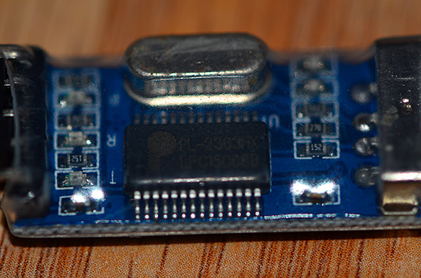
Before I can trouble shoot the A6 Module, I ended up having to trouble shoot the USB to TTL (PL2303HX) module that I was using. I have ordered this USB to TTL module some time ago thinking it would be useful one day. That day has come and unfortunately, my windows 10 PC would not cooperate and connect with the TTL device - reporting a code 10 error.
I have gone through many web pages and finally got to this link and this is perfect. It solved my connection issue. This article talked about counterfeit Prolific PL chip and this may also apply to your device if you bought it off ebay for nothing more than a couple of dollars. All you need to do is download and install the driver from that page.
To communicate with the A6 module through the TTL device, you will need to download an emulator. I am using this emulator called Terminal v1.93b, you can download it from here.
Once you start up the Terminal software, you should select the correct COM port and change the baud rate to 115200. Then click connect. You are then online with the A6 Module.
The A6 Module follows the AT command protocol. So for example, if you type "AT" at the prompt near the bottom and have the "+CR" checkbox ticked and click "SEND", an OK message should be received back from the A6 to indicate all is ok. (Hint: always have the +CR ticked as otherwise the AT command wont work). Mine is fine up to here.
And when I tried to dial a number using the command "ATDxxxxxxxxxx" where xxxxxxxxx stand for the phone number, I received back an error. I was scratching my head. Then I thought I would try resetting the PIN on the SIM card using the A6 module. The command for resetting the PIN is "AT+CPIN=pppppppp, PPPP" where pppppppp is the PUK code and PPPP is the new PIN.
By sheer luck, this fixes the connection issue and the A6 module is now fully functional and issuing command like ATD will dial the number and dialing the SIM card from another phone will now produce a ring tone instead of unconnected message.
The only limitation is that everytime the A6 module is power off, it would require the above command AT+CPIN again to initialise the SIM card. I have overcome this by including this command in the sketch.
I normally use Arduino MEGA but I have also got a new Pro Micro in my drawer (I got a pretty big drawer full of goodies!!!) , so I thought I give the Pro Micro a try.
I learned that you must set up a software serial port on the Pro Micro to link with the A6 Module. The software serial port is defined in the sketch as PIN 8 and PIN 9.
There are many ways you can trigger the text message thru the Arduino controller, for now, I just define an Input PIN (PIN 7) and when that PIN is pulled low, it will trigger a text message. An easy application would be link it to your Burglar Alarm and then when the alarm is triggered it can drive PIN 7 low to send the SMS.
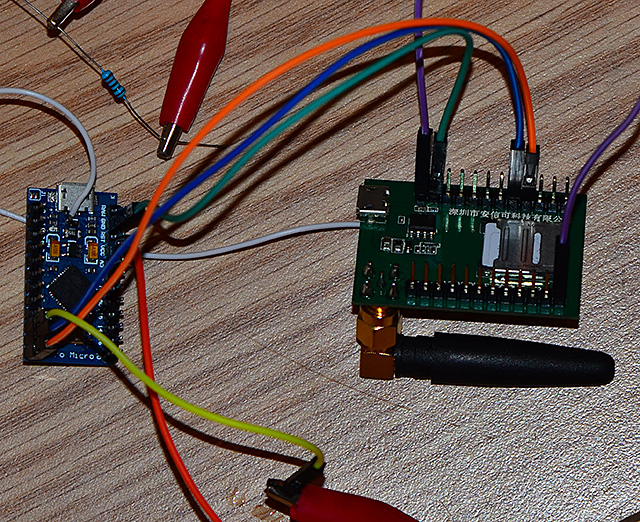
I used a pull up resistor on PIN 7 to VCC. In order to provide power via 1 USB across the pro micro and A6, I have soldered a white cable between the +VCC out of the 2 USB port. Also I have a jumper between VCC5.0 and PWR on the A6 Module to switch it on when power first applied (instead of holding that power button!)
Here is a picture of how I linked everything together.
Here is the sketch I am using. You can make use of this sketch by inserting the recipient mobile number and the Text message. (Hint: you must switch on the GSM A6 Module at the same time you switch on the Arduino board, otherwise the setup sketch will not be executed to the A6 Module!)
I would also recommend that you set an upper limit on text messages - like no more than 50 messages in a single day (which I havent done in the sketch). The last thing you want is that an error in coding or components failure is triggering thousands and thousands of text messages which the Arduino is quite capable of! Ouch.. the phone bill!