DO NOT ATTEMPT THIS REPAIR UNLESS YOU ARE EXPERIENCED IN WORKING WITH 240 V CIRCUITS. Let’s be very clear: if you don’t know what you are doing, THIS CAN KILL YOU.
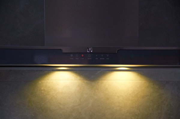
Well a bit of background. I have been using LED lights with E14 base in this rangehood. And one of the LED lights has failed, in trying to repair that LED, I managed to short the lighting circuit. The bad news is that now the lights are permanently ON .. even when it is supposed to be OFF.
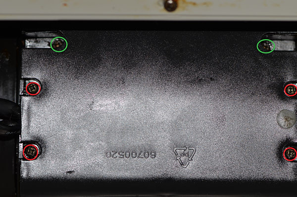
It is relatively simple to get to the control board. Safety first, unplug the machine from the power point! Then remove all 3 filters. Next, locate the main control board housing which is situated just behind the motor. Remove the 2 screws (circled in green in the attached photo) that held the housing onto the motor assembly. The housing should drop down a bit and then you can go ahead and remove the 4 screws (cicrcled in red) that are holding the housing lid. Once you removed the lid, you will be able to get access to the control board.
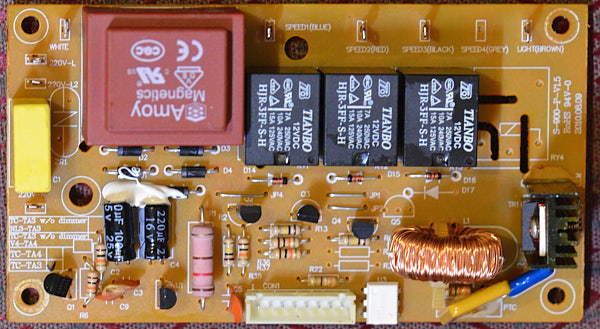
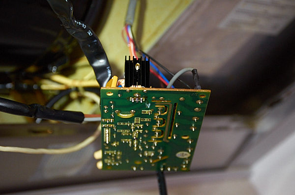
If you want to take out the PCB, you can remove the 2 screws holding the PCB to the housing and then remove all the cable connectors. Dont forget to take a picture of all the cables beforehand, so that you know which cable goes to which connector. As I found out later, you dont have to remove all the cables to repair the PCB. It is a little trickier but it can be done and this may save you some work!
Here is the schematic diagram of the control board.
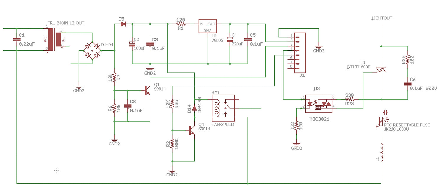
The control board has a fairly simple design. It accepts input from the touch panel through J1 connector. It then controls the fan speed. There are 3 separate relays to control the fan speed Hi, Med and Lo. If your rangehood has 4 Fan Speed, there will be 4 Relays. The schematic only shows one of these relays - RY1 for illustration purpose. If your rangehood has any issue with the fan speed - I would check the transistor S9014 that drives the relay.
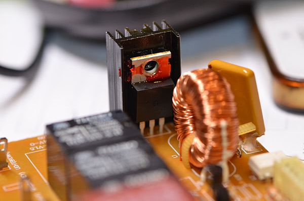
OK. Back to the lighting circuit. The IC U3 (MOC3021) receives the ON signal from the Touch panel and then switches ON the TRIAC BT137-600E that controls the light.
In my case, as the light is permanently ON so I went straight to the TRIAC and lo and behold, it is shorted. So replacing that TRIAC fixes the issue.
As I mentioned earlier, if you have the flexibility :-) and the ability to tilt your head to the most unusual angles, you can leave all the cables connected and desolder and solder components off the PCB.
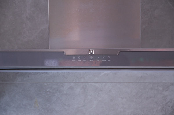
Now if your issue with the light is that it fails to turn on but the indicator light on the touch panel is working. Obviously, first thing to check is to make sure that the base of the light is making good contact with the socket. After that, then you should check the TRIAC, the PTC Resettable Fuse and finally the MOC3021 in that sequence. If your touch panel does not respond to anything .. ie. indicator lights not working, then the touch panel is faulty as long as there is 5V supplied through PIN 2 of J1.
I wouldnt be surprised that this control board is a generic design used in quite a few Electrolux and Westinghouse touch controlled rangehoods.
💬 Have thoughts? Leave a comment or question below — I read every one!