28 Feb 2017
The moment you pressed the power switch, it will attempt to start for 5 seconds, but then switched off with a blinking red LED.
A look at the manual says that it has entered into ASO/DC detect protection mode. ASO is to ensure the Amp is not overloaded due to shorted speaker terminals. And DC Detect is to protect expensive speakers in case there is malfunction within the Amp circuit.
The hardest thing to do in this situation is to keep the damn thing switch on so that one can take some measurements.
Now if your unit goes into protection with a fast blinking LED (2 blink per sec) instead of a slow blinking LED (1 blink per sec), you can try the following trick to keep it switch on. But make sure you removed all your speakers connection before you do this as you dont want to blow your expensive speakers as this will override the protection mode.
On most Denon and Marantz AV receivers, there is a 5 pin plug coming from the Amp board to the HDMI board with these labels - Thermal A, Thermal B, ASO Detect, DC Detect3, DC Detect 4. On this unit, the connector is called BN704.
To override the protection, disconnect the plug from the HDMI board. Use some cables to connect up the Thermal A and Thermal B pin (only those 2 pins) between the disconnected plug and the socket on the HDMI board. (hint: Arduino male and female pin cable is perfect for this). This should allow you to keep the unit on briefly to do your diagnosis. (hint: keep the power ON diagnosis as short as possible).
Now you need to determine whether it is ASO or DC Detect that triggers the protection. So with your DMM set to Voltage and negative to the chasis ground, measure the pin voltage of each of ASO, DC Detect3 and DC Detect 4. The one that has more than a few mV is the culprit.
My unit measures 2.6 Volt in the ASO line and that is what triggered the protection.
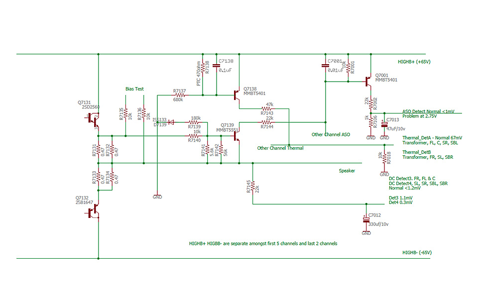
Sometimes ASO can be triggered by a problem with the amplifier circuit, other times, it could be due to faulty components in the ASO protection circuit itself. Refer to the following schematic which is an extract showing all the relevant protection components.
First step, you have to take the AMP board out. Just removed all the cables and ribbon connectors. Then unscrewed the 7 screws (3 at the bottom and 2 on each side) that are holding the heatsink to the chassis.
Then you have to find a power source to power the amp if you want to take some voltage measurements with the AMP board out. . You will need to connect power to 2 separate connectors on the board as the last 2 back channels power are supplied seapartely vs the first 5 channels.
Hint: if you want to do frequent amp repair, having a +/- high DC voltage source is invaluable. If you dont have one, just buy an old faulty amp on ebay for not much more than $2 (hopefully with an ok transformer!) and re-use its transformer/ power supply. Try to ensure that the voltage is no higher than the voltage of AVR3312 (which is +/- 65V DC) or whatever you are repairing. 10 or 20V lower should present not much problem for diagnosis.
If you dont have access to this, then you will have to do your diagnosis by measuring the components the traditional way. Power off and use your DMM to figure out which components have faulty values.
To detemine if it is faulty amp or protection circuit fault, then the next step is to measure the voltage across the output resistor (R7131/R7132). You can simply go to the bias adjustment test points (hint, those brownish 3 pin sockets - use the 2 outer pins and ignore the centre pin) on the board. If all the measurment are no more than a few mV then congratulations, you have confirmed that your amp is good.
Referring to the above schematic, transistor Q7139 turns on if the current across the output resistors (R7131/R7132) are too high. You can measure the voltage in the base and collector of Q7139. The base should be close to 0V and the Collector should be close to the Postive rail voltage (eg. +65V).
Hint: the components on each amp channel (there are obviously 7 of them) have the same 1st, 3rd and 4th digit. Only the 2nd digit is different to denote the channel. So Q7139 is the same as Q7239 on another cahnnel.
Unfortunately the protection cirucit components are on the foil side of the PCB. So you will have to unscrew the 5 screws holding the PCB to the heat sink and then gently open the PCB and heatsink like a book to about 90 degree. That should give you enough room to work with.
In my case, I found that one of the transistors (Q7639) is leaky and its collector has a much lower voltage. Due to the leak , it switched on Q7001 even though there is no voltage on its base. Through the resistor network (R7106 and 7002) on Q7001 collector, it will generate a small voltage (1/23 of the positive supply voltage - hence the 2.6V) to the CPU on the HDMI board to indicate that there is a problem with the ASO.
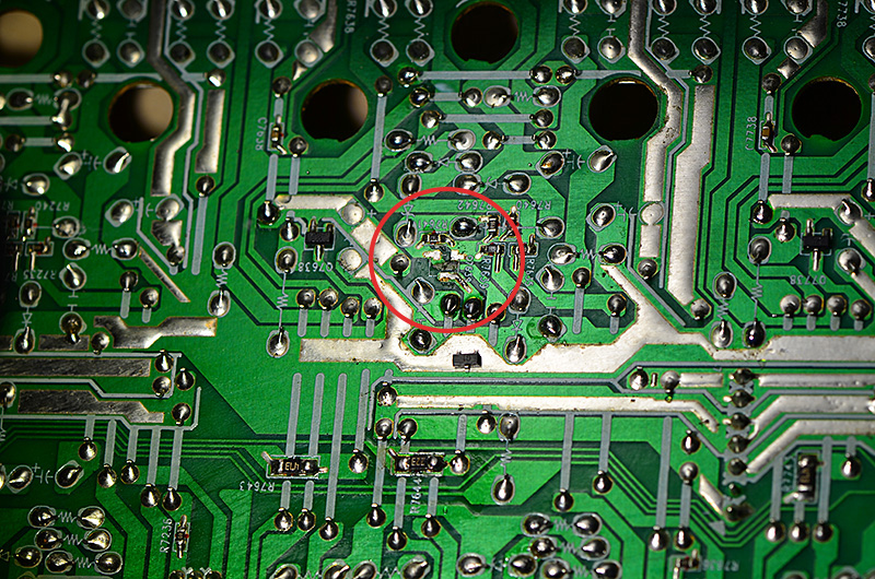
here is a picture of Q7639 - already removed from the PCB.
Replacing Q7639 is straight forward and the unit is happily working again. Not bad for something you can fix for not much more than 10 cents.
This article hopefully give you some ideas of how the protection circuit work on Denon and Marantz AVR. (They are very similar design). Mind you, when the protection is really indicating something wrong, then the repair would more likely to be around the output transistors and their related components - that will be another article for another day!
©2016 - Thomas Zih. All Rights Reserved